
Viper Force Transducer Installation Guide
Installing the VFT with Invictus SSC Base
Installing into Cougar Housing
PREFACE
The Viper Force Transducer (VFT) functions through the use of strain gauges, which measure the amount of strain or deflection of an object when force is applied. Strain gauges are sensitive in nature. You should avoid touching or handling any of the wiring of the strain gauges or the strain gauges themselves as much as possible.
The VFT was developed to work with the Thrustmaster® HOTAS Cougar. We are working on integrating it with newer systems, but as of this writing, it is not capable of functioning with any other side stick controller. The HOTAS Cougar is no longer in production, so be sure to source a used one prior to purchasing this item. Common areas to find them are eBay®, Facebook® Marketplace, or any other local online marketplace where second-hand items are sold.
The VFT is constructed to work with the original HOTAS Cougar PCB, and will work with the default HOTAS Cougar software, firmware, and drivers supplied by Thrustmaster. Our upcoming board to replace the need to connect to an old Cougar will have it's own software.
The following is a guide for how to replace the factory Thrustmaster HOTAS Cougar gimbals with the VFT. Installation is your responsibility, and Invictus Cockpit Systems assumes no liability for the installation process. Please note that the photos included are from previous versions of the VFS and may not accurately represent current parts.
PACKAGE CONTENTS
- VFT Sensor Assembly x1
- Stick Base Adapter x1
- #4-40 Phillips pan head screws x2 (installed)
- 5-pin DIN connector (installed)
- X and Y axis cables
- #6-32 bolts x8
- #6-32 Locknuts x12
- Long #6-32 bolts x4

TOOLS REQUIRED
- Phillips head screwdriver
- Allen Keys
- Needle nose pliers
- Small flathead screwdriver

Step 1: Gutting the HOTAS Cougar
- Disconnect the Cougar from your computer.
- Disconnect the throttle from the stick base and set it aside.
- Unscrew the side stick controller from the base by turning the large mounting nut.
- Unscrew the four hex nuts next to the two connectors at the front of the Cougar stick base.
- Turn over the Cougar Stick Base and remove the screws located in each of the four corners.
- Remove the bottom cover and set aside.
- Inside the Cougar Stick Base, locate the PCB and remove the four screws securing it to the Cougar stick base.

- Flip the PCB and disconnect the two potentiometer cables, and the cable that connects the PCB to the stick.
- Remove the eight screws that secure the two gimbals to the Cougar stick base.
- Remove the two gimbals. They will fall apart as you do. You may wish to save the parts in case you ever want to reinstall.
Step 2: Installing the Cougar Base Adapter
If you prefer more play in the stick, you can use the provided O-rings as outlined below. If you prefer a rigid mount, omit them. Please note that the O-rings will make the force sensors more sensitive.
- Take the #6-32 Phillips head screws and put them through the holes of the Cougar base adapter plate. If you prefer some play, put small O-rings over the threaded ends of the screws.
- Place the Cougar adapter plate over the VFT and align the eight mounting holes.
- Attach the Cougar adapter plate to the VFT with the #6-32 lock nuts. If you're using the O-rings, do not over tighten the nuts or the stick won't move.
- BE CAREFUL while installing the nuts near the strain gauge. As mentioned, the stain gauges, especially the wires, are delicate. Avoid touching them.
-
Now is a good time to install the X and Y axis connector cables. With the writing on the PCB oriented with the forward arrows pointing away from you and the gold knobs of the blue trim potentiometers pointed at you, the Y axis is the connection header farthest from you and the X axis is the one closest to you.


Step 3: Sensor Assembly
- Locate the steel ring atop the Cougar stick base that keeps the dustcover in place. Replace the four Phillips head screws in it with four long #6-32 Allen key bolts. Drive them all the way in and secure them tightly.
- Replace the eight gimbal mounting screws from Step 1 to prevent dust entering the Cougar stick base. Preventing dust intrusion is their only use.
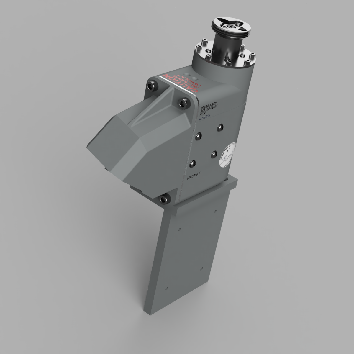
- Feed the assembled VFT through the square hole at an angle as shown below. It is a tight fit and may require you to file the square opening some to get it through.

- Place the VFS with adjustment screws located to the back side of the Cougar stick base.
- Slide the VFS over the previously mounted long #6-32 screws and use four #6-32 lock nuts and washers to secure the VFT in place.

Step 4: Installing the PCB
- Reattach the stick PCB connector to the Thrustmaster PCB.
- Connect the sensor cables to the PCB.
- Reattach the Thrustmaster PCB to the Cougar stick base in its original position using the original screws. Do not forget to reattach the grounding wire.
- Reinstall the bottom cover using the original screws.
The VFT is now installed in the Cougar Stick Base.
Step 8: Manually Calibrating Your VFT
- Reconnect your HOTAS to your computer, and open the HOTAS CCP software.
- Go to the start-up & calibration tab.
- Click manual calibration.
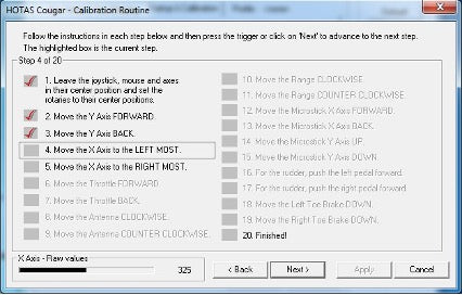
- Go to the point where the software directs you to move y-axis forward, and adjust the y-axis trim pot using a small flathead screwdriver until you get a raw value of 324. You will not need to calibrate the Y axis back. The value will be correct from the previous step.
- Click next until the software directs you to move the X-axis to the left most, then turn the x-axis trim pot until you get a raw value of 324. You will not need to calibrate it to the right.
- Jump back to step 1 of the calibration menu.
- Now finish the calibration following the calibration steps of the HOTAS CCP menu.
Curves and Dead Zones
Depending on how and where you mount your Cougar stick base, you may need to adjust the sensitivity of the stick. The sensitivity can be controlled by the curve settings in the HOTAS CCP axis shaping tab. Adjusting the curve is a matter of personal taste.
You can also set the dead zones, and they will not affect the curves. We recommend a dead zone of 10 for the center of both the X and Y axis.
Mechanical Center Play
You will experience some mechanical play in the stick while using the VFT. Tightening the screw on the bottom of the stick may resolve some of the play, but it will eventually return. The TPU deflection gasket will eliminate most of this by holding the nut in place with friction.
This horseshoe part below is another option to prevent the nut from backing out, but is omitted from the newest version. If you have issues with the large attachment nut backing off, let us know and we will send you a part to help secure it. (Or send you a file to print it yourself if you have the capability)

Installing into Non-Invictus Stick Base
NOTE: Invictus Cockpit Systems makes no claim that our VFT will fit any stick base we did not make. It is up to the buyer to ensure fit before ordering. Review the datasheet.
PACKAGE CONTENTS
- Viper Force Transducer x1
- #4-40 Phillips pan head screws x2 (installed)
- 5-pin DIN connector (installed)
- X and Y axis cables
- #6-32 bolts x8
- #6-32 Locknuts x8
- TPU Deflection Gasket
- ASA Din connector Spacer
TOOLS REQUIRED
- Allen Keys
- Small flathead screwdriver
Step 1: VFT Connection
- Place your VFT upside down on a table with the PCB pointing up. Orient the VFT so that the two brass screw knobs on the blue square potentiometers on the PCB are pointing at you.
- Connect the 5 pin connector from the VFT to the 5 pin connector of the Thrustmaster Cougar HOTAS PCB.
- Connect the 3 pin connector wire labeled X Axis to the 3 pin connector on the VFT nearest you.
- Connect the 3 Pin connector wire labeled Y Axis to the 3 pin connector on the VFT farthest from you.
- Connect the X Axis wire to the X Axis connector on the Cougar HOTAS PCB. The X Axis connector is labeled, but just in case it is hard for you to see, it is on the same side as the 5 pin connector.
- Connect the Y Axis wire to the Y Axis connector on the Cougar HOTAS PCB.
Step 2: Manually Calibrate Your VFT
- Using the original Cougar PCB USB Cable, connect the device to your computer.
- Open the Cougar CCP on your desktop.
- Navigate to the start-up & calibration tab.
- Click the manual calibration button.
- Click next until the software directs you to move y-axis forward, and adjust the brass screw on the blue trim potentiometer on the VFT PCB using a small flathead screwdriver until you get a raw value of 324. You will not need to calibrate the Y axis back value as it will carry over.
- Click next until the software directs you to move the X-axis to the left most, then adjust the brass screw on the x-axis trim potentiometer until you get a raw value of 324. You will not need to calibrate it to the right as the value will carry over.
- Jump back to step 1 of the calibration menu.
- Now finish the calibration following the calibration steps of the HOTAS CCP menu.
- Once your VFT is calibrated to your environment, disconnect the wires from the Cougar PCB, feed them through your stick base, and then reconnect them.
- Install the eight mounting screws into your stick base. Recheck your calibration. (Review the VFT datasheet for hole mounting patterns to ensure your stick base will accept the VFT)
It is important to note that any changes to the environment may affect the calibration of the VFT. Changes in temperature, humidity, etc. can affect it. Additionally, the strain of screwing the VFT into a stick base will also throw off the calibration. For this reason, our stick bases have access holes to allow you to adjust the trim potentiometers while the VFT is in place. If you do not have them, you may need to adjust the torque on various mounting screws around your stick base to find the sweet spot.
Curves and Dead Zones
Depending on how and where you mount your VFT, you may need to adjust the sensitivity of the stick. The sensitivity can be controlled by the curve settings in the HOTAS CCP axis shaping tab. Adjusting the curve is a matter of personal taste.
You can also set the dead zones, and they will not affect the curves. We recommend a dead zone of 10 for the center of both the X and Y axis.
Mechanical Center Play
The Thrustmaster sticks are notorious for the mounting nut to back off during use, which creates mechanical play in the stick. Tightening the screw on the bottom of the stick may resolve some of the play, but it will eventually return. The TPU deflection gasket will eliminate most of this by holding the nut in place with friction.
This horseshoe part below is another option to prevent the nut from backing out, but is omitted from the newest version of the VFT as it is no longer necessary for most users. If you have issues with the large attachment nut backing off, let us know and we will send you a part to help secure it. (Or send you a file to print it yourself if you have the capability)